Some of you may have noticed that I have failed to post for some time. I have a good reason for most of it.
Over the course of the past month I have completed my Master of Engineering degree. I completed my final courses, and successfully defended my research.
Here is some of what I did this past semester while working on the ANDERS for Bridge Decks Project. The part of the project I was associated with was the bridge repair part. My job was to design and redesign components for the robot.
This is where the project was when I first became involved, the robotic arm would be attached to the robot and the drill would drill holes in the road.
These where the first two things I designed. On the left is a device that can be pressed against the concrete around the hole that was drilled (the black part is rubber) and sealant would be pumped into subsurface cracks in the concrete to repair it. On the right was a design for a two part epoxy mixing device. Two different components would be pumped in from the top and forced to mix as they run through the device.
This is what my first design was modified into. The change was for ease of construction and because it used materials I already had on hand. It is effectively the same thing as the previous design with an added load cell to measure how much force the unit would be pushing down on concrete with.
Now we are moving on to the next part of the project. The whole drilling and sealing system. I decided that it would be most efficient if we where to use the same screw rail being used to actuate the drill to also actuate the sealer.
The next step was to improve upon the design of the drill mounting. I took advantage of existing mount points on the motor housing inside the drill to shorten the end effector. Additionally, you will note an intermediate design for the sealer attached to the design.
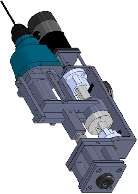
I wanted to see how compact I could make the entire end effector. So I removed the load cell (large short cylinder mounted between the drill and the screw rail) and moved it to the robot arm. With this removed i could make is as compact as possible. However, I also needed to invert the motor that powered the screw rail (black, silver and gray cylinder) because otherwise it would hit the ground. Additionally, if you look between the previous design and this one you can see a small black ring attached to the backside of the plate holding the screw rail together. This is how the end effector connects to the robot arm. You can see from the placement that in the compact design it is much closer to the inertial center of the end effector. This means that it would be much easier for the robot arm to rotate it the 180 degrees necessary to switch between the drill and the sealer.
My adviser did not like the compact design so he asked me for a combination of the compact and non-compact design (also not liking a number of intermediate designs). The result is above. The load cell has been moved but the screw rail and its motor are in-line with each other.


No comments:
Post a Comment